Showing posts with label field test. Show all posts

Friday, January 6, 2023

Delta Loop vs End Fed Half Wave on 20m

Recently I came across a post by a German OM DL3TU who was quite pleased with the results of a delta loop on 20m.

I have a delta loop for 40m but rarely use it as it is quite big. For 20m a delta loop becomes very manageable. 

As my best DX antenna - the portable hexbeam - is not always an option from a time, effort or space perspective, I am always curious if there is another design that could beat my default go to option: the vertical end fed half wave antenna.

So I read through the notes of DL4AAE (who designed the antenna DL3TU wrote about) and built the same antenna. The nice thing about the version he designed is that it has an impedance of around 50 ohm. The design I used for 40m has 75 ohm and therefore needs some matching solution (like a quarter wave piece of rg59).

The new delta loop
Two antennas in the field
One of the beacons

This afternoon I went out to test the effectiveness of the antenna as compared to the 20m EFHW vertical. As always I did this by running two identical WSPR beacons for a while. I didn't have a lot of time before sundown so the dataset was put together over 30 minutes in which both beacons transmitted 9 times.

After examining the WSPR signal reports I found an interesting outcome.


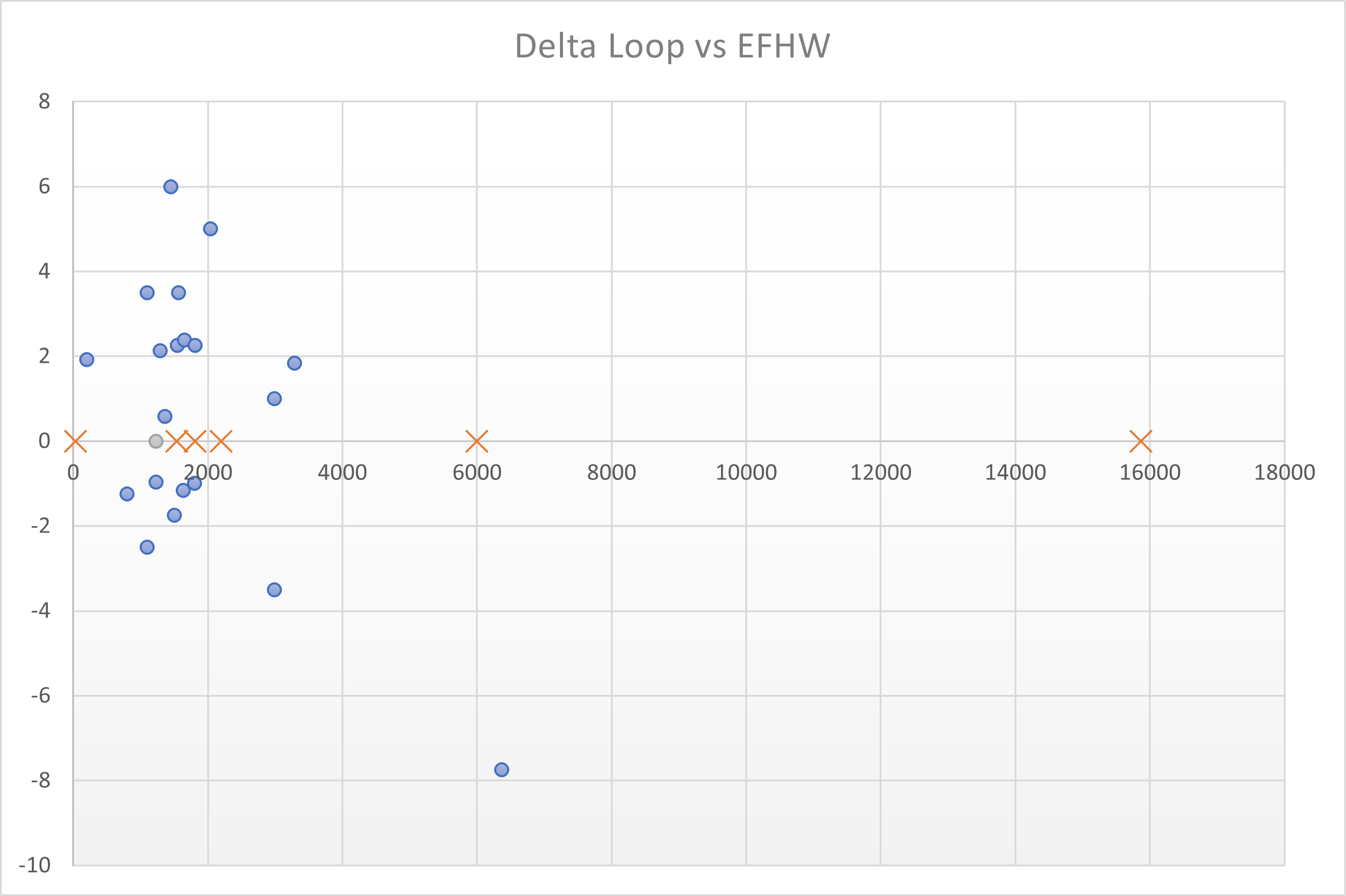
Blue points are the averaged differences between the signal reports of the same spotter for the Delta Loop over the EFHW. The spotters are plotted by their distance from me.

The plot shows that in EU to about 3000km the delta loop beats the EFHW at most spotters, although four spotters only heard the EFHW (orange cross) and the EFHW got more reports in total. So it would probably be hard to tell the difference between the two within EU during a field activity.

Outside of EU the story is a different one. There were three DX stations picking up the WSPR signals. W7, VE6 (6000km) and VK5 (15000km). The VE6 copied both beacons a couple of times but the EFHW was clearly stronger (by average 8dB). The W7 only copied the EFHW but only barely and once - so we will skip that one. The VK5 copied the EFHW 4 times without picking up the delta loop beacon. 

The delta loop deserves a bit more testing but at first sight I would choose the EFHW for both its performance and practicality.


Saturday, January 15, 2022

Mobile whip versus end fed half wave vertical

Those who have read previous reports of my portable activities know that I usually put in quite a bit of effort to set up a DX worthy station in the field - when possible using my hexbeam and a bit of power.

On the other end of the scale I still have a mobile antenna laying around from when I re-started the hobby in 2010. The antenna is known as D-Original DX-UHV and had some glaring reviews at the time. I did work across the pond to W with up to 7500km in phone and to PY and LU on psk31 (11.000km).

Quite quickly however I moved on to using end fed half wave wires for my portable activities, trying to cover more distance. 

Noticing that there are a number of castle (WCA) and nature reserve (WWFF) activators that use a mobile antenna, I was wondering how effective that antenna actually is. I have no doubt the end fed wire is superior to the mobile antenna, but how much better is it? Should I consider going back to using the mobile antenna?

So time to bring out the two WSPRLite beacons (two identical 200mW WSPR beacons that I can use simultaneously) again and head out to my test location north of Arnhem. My reference antenna is a half wave end fed set up vertically - or almost vertically in the case of the 40m version as the pole I use is 18m high. 


I started out with the 20m configuration of both antennas. The mobile antenna is in this configuration 147cm long. I chose to bring the feed point of the end fed wire about 2m off the ground as I have used this set up as a reference in other tests as well - and it is a set up that would only require a 12m pole so probably more relevant to the average activator.

For the second test of the 40m configurations, I fully extend the 18m pole and then sloped the last couple of meters of the end fed wire so that the feed point was about a meter of the ground. This is how I usually set the 40m end fed up in the field. On the mobile antenna I changed the element for 20m to the 40m version (the antenna is then 195cm long). The DX-UHV antenna can hold two different elements at the same time but for this test I decided to use one at the time.

As expected there is a clear winner on both bands - not surprisingly this is the vertical wire. The question I had was how much the two would differ. Here is a breakdown of the data I managed to collect in the time I had (1 hour on 20m and 1 hour on 40m), 

Results on 20m

On 20m in 1 hour:

  • DX-UHV - 16 transmission - 56 spots - 11 spotters
  • End fed half wave wire - 16 transmissions - 118 spots - 24 spotters
DX-UHV did reach NAEnd fed wire copied by the same and more

Odx for the mobile antenna was 6000km to W2. Odx for the end fed wire was 8000km to W7. 
There were not a lot of stations that copied the signal from the mobile - less than half of the stations that copied the beacon on the end fed wire. There were 6 stations that copied both signals multiple times. Looking at the reports from these stations there is an average 9dB difference in the signal strength reported. 

Results on 40m

On 40m in 1 hour:

  • DX-UHV - 15 transmissions - 119 spots - 27 spotters
  • End fed half wave wire - 12 transmissions - 317 spots - 56 spotters

DX-UHVEnd fed wire

Odx for the mobile antenna was 2200km to SV8 (1 spot -29dB). Odx for the end fed wire was 3100km to EA8 (7 spots). Looking at the reports of stations that copied both signals multiple times, there is an average 10dB difference in the signal strength reported. 

On 40m the difference is more pronounced looking at the amount of spots. With less transmission cycles of the beacon the end fed wire reaches more than twice the amount of stations. The reach is considerably longer with TF, TA, 5B4 and EA8 only copying the end fed wire.

Conclusions

So what have I learned.. well the outcome really matches my expectations. 

Looking at it from the practical side, the mobile antenna is easier to set up and does not take any more space than the car itself does at the activation location - can be a huge plus in some places. It also requires a lot less room in the car so it might open up a few more possibilities for /P operations.
 
The consequences however are that I will reach less stations and especially less DX. I have also found that controlling a crowded frequency is more difficult if your own signal is relatively weak. On the other hand... it might not be so crowded if no one hears you (hihi) 

The difference is considerable but not overly dramatic though, when conditions are good and signals are around S9 on the end fed wire, you would still put in a good S7 with the mobile antenna. So I will give it a try in an activation when conditions are favourable and simplicity is important for whatever reason. tbc. 

This post is one of a series of antenna comparisons I have done. The index to the other tests is here,

Friday, August 7, 2020

40m wire antennas compared

Before going on holiday I managed to get some life into my old C-Pole using a new home made choke. I re-tuned the antenna (with some challenges) but did not get a chance to use it. 

In the past I did use it quite a bit and was pleased with the results but as always - this does not tell you a lot. HF conditions vary too quickly and dramatically to base any evaluation on single antenna experiences. You really need simultaneous A/B testing.

A gap in my schedule allowed me to go out and do some testing of different wire antennas for 40m. I ended up testing a C-Pole versus an end fed halve wave more or less vertical and the same C-Pole versus an inverted V dipole.


Test setup

I used two identical WSPRLite beacons that transmit with 200mW on the WSPR frequency. 

  • The C-Pole was set up so that the feedpoint was at approx 2m above ground (that would be your typical setup with a 12m pole, like the Spiderbeam I have - with the top of the antenna at 11m). 
  • The EFHW was attached to my 18m pole and therefore almost vertical. The last 3-4m I set up sloping so that the feedpoint was at approx 1.5m above ground.
  • The Inverted V was set up so that the feedpoint/apex was about 13m high. 

The test period was the end of the afternoon. Not the best time for 40m and certainly not the best time to test DX performance. However it was the time I had available. 


C-Pole meets EFHW vertical

The first run was the C Pole vs the EFHW vertical. I let the beacons run for about an hour. After that time I had:

AntennaTransmissionsSpottersSpots
C-Pole1560328
EFHW1560392

On first glance the EFHW vertical seems to fare better. It has been heard more often. However both antennas reached the same amount of spotters. So nothing too dramatic here. There is not a lot of difference in the stations that received the signals - so most of the spotters returned data for both antennas.

Now looking at the SNR reported by the spotters there is more to say about the difference. I averaged the reports per spotter to decrease the amount of data points. The graph below shows the signal strength reported (SNR in dB on the Y axis) at the spotters' distance. It looks like the EFHW (in orange) performs better.

I then calculated the average difference in signal strength per spotter of the EFHW over the C-Pole - so only for spotters that returned reports for both antennas. The graph shows the difference the EFHW scored in dB - above the line means the EFHW beat the C-Pole. 

This clearly shows the EFHW beats the C-Pole on almost all distances and sometimes by a fair margin. The outlier is S51RS at 950km. That is the only spotter favoring the C-Pole significantly.

So if you have enough height available the EFHW is the one to choose out of the two at least for the ranges tested today. This is what I expected from the theoretical analysis I did some time ago.

An interesting followup would be to see how the EFHW would perform with the same top height (sloping from the 12m pole or tree branch). With a slingshot one can easily get a vertical wire up 20m, so I would normally aim for that height with this antenna.

C Pole meets inverted V dipole

Now how about the inverted V? This one adds another element to the game as it is horizontally polarised (as opposed to the vertical EFHW and the C-Pole).

I chose a height around 13m (not fully extending the 18m pole). In retrospect I might as well have gone 2 meters lower to compare the antenna if set up on the same 12m pole as I used for the C Pole antenna. Here we have a slight advantage for the inverted V.

Running the beacons for just under an hour I had:

AntennaTransmissionsSpottersSpots
C-Pole1045202
Inverted V1146219

The inverted V got one extra shot so it is hard to tell from this first glance which one performed better. 

Looking at the average report per spotter shows that the Inverted V (in green) seems to beat the C-Pole on most occasions. 

Moving one step further the indication is confirmed. The Inverted V wins (above the line) almost everywhere. The biggest outlier again is S51RS.

Conclusions

I did not test the inverted V against the EFHW vertical directly. However looking at the differences per test, using the C-Pole as "a reference antenna", there does not seem to be a lot of performance difference within EU. I would have expected the inverted V to do slightly better than the vertical on the shorter distances (with its higher radiation angle) but that might be only noticeable on even shorter distances.

So, this time I learned that within EU the C-Pole loses against an inverted V at more or less the some top height and loses against a vertical EFHW with the feedpoint at more or less the same height. 

One question remains - as the antenna's have different radiation patterns - would any of these clearly beat the others on multi hop DX? The simulations I did previously would suggest that the C-Pole would have an advantage over the inverted V because of more low angle radiation.

If it turns out the C-Pole does not "deliver on promise" there, then I cannot see a lot of situations where I would choose it over one of the other designs. Only if the footprint needs to be minimal and height is restricted (*).

This last question requires a new test around gray line time - when I can't use my favourite test ground as it is only accessible in daylight. Something to put on the "to do list".

*) Another one: would the C-Pole beat a shortened 40m EFHW of equal height - so approx. 12m? I have such a wire with spool that I used in the past for my 10-20-40m EFHW.

Wednesday, April 29, 2020

C-pole tuning part 3

This weekend I went out to test my C-pole with a new 1:1 balun. As I blogged before I ran into trouble with this antenna and the common mode choke I constructed in W2DU style.

To rule out any balun influences I had decided to tune the C-pole last week using my VNA without any balun present. My idea at the time was that this would give me the most clean picture of the antenna and would rule out any failure of the balun ruining the tuning process. Smart move? No. (but I learned something).

While working on the "naked" antenna I was amazed how much off it was. To me at the time it seemed strange (I tuned it before didn't I?) but it did explain why it failed in operation. So I continued re-tuning the antenna - moving the feedpoint a considerable bit along the one leg of the folded dipole (basically the C-pole is a dipole with the ends folded in a square shape towards each other).

After 1,5-2h of pushing the antenna up and down again I had a perfect match in the 40m band. One happy camper.

At home I tested and optimised my 40m balun. Ready for the final assembly and testing.

This weekend I had some time to go out to bring it all together and enjoy the fruits of my labour. However when I set up the antenna with balun I found.... it was way off. Go figure.

Tuning the C-pole yet another time

Discussing this with my YNOMY team members we came to the conclusion that the common mode current - considerable in this design - influences the measurements of the VNA. So tuning the "naked" antenna was a stupid idea and the time spent tuning was actually time spent detuning it.

A frustrated ham is never going to be the best person to work on any project but I did decide there and then to re-tune the antenna one more time. I was almost finished when I too hastily bumped the VNA against the pole. The center conductor of the SMA plug attached to the VNA broke off and is now securely in place in my VNA port - making it neither a female nor male connector (gender neutral - a modern concept). That concluded the tuning process for the time being.  

Gender neutral SMA connector

So now I have to replace the SMA connector on the VNA. That connector - I found - is soldered into place with lead free solder that I cannot remove with my soldering iron as it just does not heat up enough.
Luckily Marcel PG8M told me he both has the connectors and a proper soldering iron. So now I have to find the time to go over to his place and have him repair the damages (keeping a safe distance all the time of course).


Sunday, April 12, 2020

Up a tree - part 2

After dusting off my EZ-hang slinghsot I replaced the old and in the meantime shortened fishing line with new fluorescent line (0.25mm). I started out with 120m but that was a little too much for the reel so I cut it back to 100m.

I was wondering what the effect of the different sinker weights would be in practice - which one would travel higher and how would they behave once up in a tree.


Slingshot with 1.75oz sinker
Slingshot with original sinker

First I did some simple shots across a field. It turned out both weights ended up at around the same distance: 50m (170ft) with a maximum of 54m for the 1.75 oz weight and 58m for the original 1oz weight. I would say comparable.


Lots of nice branches
Then I selected a few nice trees to compare the two sinkers further. Again the difference in height reached was not really significant. Both ended up around 25m (80ft) with the 1oz weight reaching the highest branch at 28m (90ft). This corresponds to the highest mast I have (26m) so more than acceptable.


Two differences were significant to me:

1. the original (yellow) sinker was easier to find (higher visibility thanks to the paint)
2. the heavier sinker came down smoothly every time while the original one had to be helped down more than once (tugging the line)

So I think it is a matter of painting the heavier sinkers and I am good to go.


Another thing I will optimise are the rubber bands of the slingshot. They can be stretched quite lightly even up to my maximum reach. As it turns out (as with everything you dive into) there is a whole unknown territory to explore when it comes to designing good slingshots. Another thing to put on the to-do-list. On top of that list is figuring out why my 40m c-pole antenna kills current chokes. More on that later...


The "chosen one" in action

Friday, April 3, 2020

Up a tree

Being confined to home during the whole week - working remote through video links - I was looking for an outdoor activity. I decided to do some testing on my various options of launching wire antennas in a tree. Being able to deploy an antenna at a decent height without a mast increases the options for effective activities /P. 
In my little test this Sunday I used two different weights and my slingshot (by EZ Hang).

When I started looking for ways to get a wire up a tree I tried various objects and lines. I found out quickly that it is important that the wire is smooth - so fishing line or decoration line (used in shop windows for example) is the way to go.


Decoration and fishing line

As to the object to throw you need something that is easy to handle, smooth / round (so it glides through the branches) and a convenient throwing weight. Regarding the weight you are looking for a sweet spot: heavier and it will get difficult to throw high, lighter and the object will not return your line back to earth but just keep on dangling somewhere high up in the tree. In that situation you are left with tugging the line hoping the object continues its descent but in my experience you might just as well cause the object to swing around the nearest branch - leaving it behind for eternity. 

I started out with a ball as throwing object. Trying different types I settled on a field hockey ball. The reason being that it fits my hand perfectly and the weight is around the sweet spot (150gr) - not too heavy but generally enough to bring the line back down. Just drill a hole through the middle and away you go.

The ball is kind of large though so not so practical to carry around. Later on I started using fishing sinkers, settling on the heaviest one I could find (90gr). 


Throwing weights: hockey ball and fishing sinker

I tried both and measured the height I could get a line up. Of course it is slightly unscientific as I used only one tree in this experiment - so not all heights were achievable only specific branch heights. It turns out I can throw the fishing weight just a bit higher than the ball. A few tries brought it up to 12 meters / 40 feet. A decent height for a wire antenna on the higher bands.


EZ Hang slingshot

Then I turned to my slingshot. I have been struggling with it in the past, getting the line stuck in the reel or not having the ball come down from the tree (losing a lot of line).

After a few tries I did manage to shoot the provided metal ball a nice way up and through the tree reaching a height of 25m. I think I can shoot it higher than that if I give it a bit more practice. That is a good height even for wire antennas on the lower bands.


The EZ hang standard weight - a 25gr canon ball

The main weakness to me is that the weight of the standard ball is too low to be sure it comes down from a tree with a lot of branches (let alone leaves). So the next thing I will do is test this out with a few different weights. I also have to replace the line as it has become too short after losing parts of it in the past (stuck in trees).


Will share more experiences in the future.