Showing posts with label testing. Show all posts

Friday, January 6, 2023

Delta Loop vs End Fed Half Wave on 20m

Recently I came across a post by a German OM DL3TU who was quite pleased with the results of a delta loop on 20m.

I have a delta loop for 40m but rarely use it as it is quite big. For 20m a delta loop becomes very manageable. 

As my best DX antenna - the portable hexbeam - is not always an option from a time, effort or space perspective, I am always curious if there is another design that could beat my default go to option: the vertical end fed half wave antenna.

So I read through the notes of DL4AAE (who designed the antenna DL3TU wrote about) and built the same antenna. The nice thing about the version he designed is that it has an impedance of around 50 ohm. The design I used for 40m has 75 ohm and therefore needs some matching solution (like a quarter wave piece of rg59).

The new delta loop
Two antennas in the field
One of the beacons

This afternoon I went out to test the effectiveness of the antenna as compared to the 20m EFHW vertical. As always I did this by running two identical WSPR beacons for a while. I didn't have a lot of time before sundown so the dataset was put together over 30 minutes in which both beacons transmitted 9 times.

After examining the WSPR signal reports I found an interesting outcome.


Blue points are the averaged differences between the signal reports of the same spotter for the Delta Loop over the EFHW. The spotters are plotted by their distance from me.

The plot shows that in EU to about 3000km the delta loop beats the EFHW at most spotters, although four spotters only heard the EFHW (orange cross) and the EFHW got more reports in total. So it would probably be hard to tell the difference between the two within EU during a field activity.

Outside of EU the story is a different one. There were three DX stations picking up the WSPR signals. W7, VE6 (6000km) and VK5 (15000km). The VE6 copied both beacons a couple of times but the EFHW was clearly stronger (by average 8dB). The W7 only copied the EFHW but only barely and once - so we will skip that one. The VK5 copied the EFHW 4 times without picking up the delta loop beacon. 

The delta loop deserves a bit more testing but at first sight I would choose the EFHW for both its performance and practicality.


Saturday, January 15, 2022

Mobile whip versus end fed half wave vertical

Those who have read previous reports of my portable activities know that I usually put in quite a bit of effort to set up a DX worthy station in the field - when possible using my hexbeam and a bit of power.

On the other end of the scale I still have a mobile antenna laying around from when I re-started the hobby in 2010. The antenna is known as D-Original DX-UHV and had some glaring reviews at the time. I did work across the pond to W with up to 7500km in phone and to PY and LU on psk31 (11.000km).

Quite quickly however I moved on to using end fed half wave wires for my portable activities, trying to cover more distance. 

Noticing that there are a number of castle (WCA) and nature reserve (WWFF) activators that use a mobile antenna, I was wondering how effective that antenna actually is. I have no doubt the end fed wire is superior to the mobile antenna, but how much better is it? Should I consider going back to using the mobile antenna?

So time to bring out the two WSPRLite beacons (two identical 200mW WSPR beacons that I can use simultaneously) again and head out to my test location north of Arnhem. My reference antenna is a half wave end fed set up vertically - or almost vertically in the case of the 40m version as the pole I use is 18m high. 


I started out with the 20m configuration of both antennas. The mobile antenna is in this configuration 147cm long. I chose to bring the feed point of the end fed wire about 2m off the ground as I have used this set up as a reference in other tests as well - and it is a set up that would only require a 12m pole so probably more relevant to the average activator.

For the second test of the 40m configurations, I fully extend the 18m pole and then sloped the last couple of meters of the end fed wire so that the feed point was about a meter of the ground. This is how I usually set the 40m end fed up in the field. On the mobile antenna I changed the element for 20m to the 40m version (the antenna is then 195cm long). The DX-UHV antenna can hold two different elements at the same time but for this test I decided to use one at the time.

As expected there is a clear winner on both bands - not surprisingly this is the vertical wire. The question I had was how much the two would differ. Here is a breakdown of the data I managed to collect in the time I had (1 hour on 20m and 1 hour on 40m), 

Results on 20m

On 20m in 1 hour:

  • DX-UHV - 16 transmission - 56 spots - 11 spotters
  • End fed half wave wire - 16 transmissions - 118 spots - 24 spotters
DX-UHV did reach NAEnd fed wire copied by the same and more

Odx for the mobile antenna was 6000km to W2. Odx for the end fed wire was 8000km to W7. 
There were not a lot of stations that copied the signal from the mobile - less than half of the stations that copied the beacon on the end fed wire. There were 6 stations that copied both signals multiple times. Looking at the reports from these stations there is an average 9dB difference in the signal strength reported. 

Results on 40m

On 40m in 1 hour:

  • DX-UHV - 15 transmissions - 119 spots - 27 spotters
  • End fed half wave wire - 12 transmissions - 317 spots - 56 spotters

DX-UHVEnd fed wire

Odx for the mobile antenna was 2200km to SV8 (1 spot -29dB). Odx for the end fed wire was 3100km to EA8 (7 spots). Looking at the reports of stations that copied both signals multiple times, there is an average 10dB difference in the signal strength reported. 

On 40m the difference is more pronounced looking at the amount of spots. With less transmission cycles of the beacon the end fed wire reaches more than twice the amount of stations. The reach is considerably longer with TF, TA, 5B4 and EA8 only copying the end fed wire.

Conclusions

So what have I learned.. well the outcome really matches my expectations. 

Looking at it from the practical side, the mobile antenna is easier to set up and does not take any more space than the car itself does at the activation location - can be a huge plus in some places. It also requires a lot less room in the car so it might open up a few more possibilities for /P operations.
 
The consequences however are that I will reach less stations and especially less DX. I have also found that controlling a crowded frequency is more difficult if your own signal is relatively weak. On the other hand... it might not be so crowded if no one hears you (hihi) 

The difference is considerable but not overly dramatic though, when conditions are good and signals are around S9 on the end fed wire, you would still put in a good S7 with the mobile antenna. So I will give it a try in an activation when conditions are favourable and simplicity is important for whatever reason. tbc. 

This post is one of a series of antenna comparisons I have done. The index to the other tests is here,

Friday, August 7, 2020

40m wire antennas compared

Before going on holiday I managed to get some life into my old C-Pole using a new home made choke. I re-tuned the antenna (with some challenges) but did not get a chance to use it. 

In the past I did use it quite a bit and was pleased with the results but as always - this does not tell you a lot. HF conditions vary too quickly and dramatically to base any evaluation on single antenna experiences. You really need simultaneous A/B testing.

A gap in my schedule allowed me to go out and do some testing of different wire antennas for 40m. I ended up testing a C-Pole versus an end fed halve wave more or less vertical and the same C-Pole versus an inverted V dipole.


Test setup

I used two identical WSPRLite beacons that transmit with 200mW on the WSPR frequency. 

  • The C-Pole was set up so that the feedpoint was at approx 2m above ground (that would be your typical setup with a 12m pole, like the Spiderbeam I have - with the top of the antenna at 11m). 
  • The EFHW was attached to my 18m pole and therefore almost vertical. The last 3-4m I set up sloping so that the feedpoint was at approx 1.5m above ground.
  • The Inverted V was set up so that the feedpoint/apex was about 13m high. 

The test period was the end of the afternoon. Not the best time for 40m and certainly not the best time to test DX performance. However it was the time I had available. 


C-Pole meets EFHW vertical

The first run was the C Pole vs the EFHW vertical. I let the beacons run for about an hour. After that time I had:

AntennaTransmissionsSpottersSpots
C-Pole1560328
EFHW1560392

On first glance the EFHW vertical seems to fare better. It has been heard more often. However both antennas reached the same amount of spotters. So nothing too dramatic here. There is not a lot of difference in the stations that received the signals - so most of the spotters returned data for both antennas.

Now looking at the SNR reported by the spotters there is more to say about the difference. I averaged the reports per spotter to decrease the amount of data points. The graph below shows the signal strength reported (SNR in dB on the Y axis) at the spotters' distance. It looks like the EFHW (in orange) performs better.

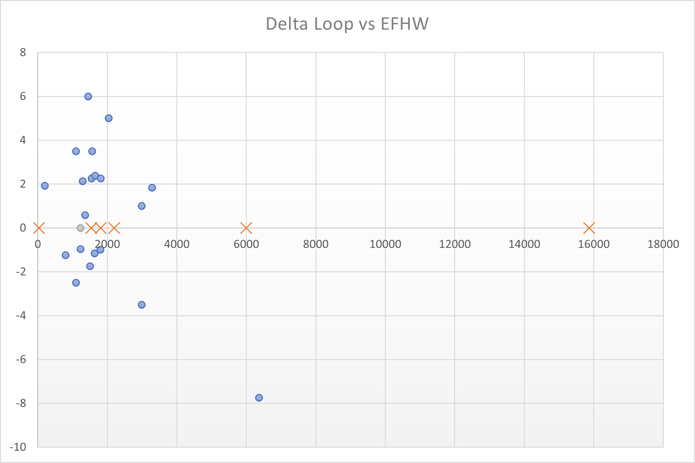
I then calculated the average difference in signal strength per spotter of the EFHW over the C-Pole - so only for spotters that returned reports for both antennas. The graph shows the difference the EFHW scored in dB - above the line means the EFHW beat the C-Pole. 

This clearly shows the EFHW beats the C-Pole on almost all distances and sometimes by a fair margin. The outlier is S51RS at 950km. That is the only spotter favoring the C-Pole significantly.

So if you have enough height available the EFHW is the one to choose out of the two at least for the ranges tested today. This is what I expected from the theoretical analysis I did some time ago.

An interesting followup would be to see how the EFHW would perform with the same top height (sloping from the 12m pole or tree branch). With a slingshot one can easily get a vertical wire up 20m, so I would normally aim for that height with this antenna.

C Pole meets inverted V dipole

Now how about the inverted V? This one adds another element to the game as it is horizontally polarised (as opposed to the vertical EFHW and the C-Pole).

I chose a height around 13m (not fully extending the 18m pole). In retrospect I might as well have gone 2 meters lower to compare the antenna if set up on the same 12m pole as I used for the C Pole antenna. Here we have a slight advantage for the inverted V.

Running the beacons for just under an hour I had:

AntennaTransmissionsSpottersSpots
C-Pole1045202
Inverted V1146219

The inverted V got one extra shot so it is hard to tell from this first glance which one performed better. 

Looking at the average report per spotter shows that the Inverted V (in green) seems to beat the C-Pole on most occasions. 

Moving one step further the indication is confirmed. The Inverted V wins (above the line) almost everywhere. The biggest outlier again is S51RS.

Conclusions

I did not test the inverted V against the EFHW vertical directly. However looking at the differences per test, using the C-Pole as "a reference antenna", there does not seem to be a lot of performance difference within EU. I would have expected the inverted V to do slightly better than the vertical on the shorter distances (with its higher radiation angle) but that might be only noticeable on even shorter distances.

So, this time I learned that within EU the C-Pole loses against an inverted V at more or less the some top height and loses against a vertical EFHW with the feedpoint at more or less the same height. 

One question remains - as the antenna's have different radiation patterns - would any of these clearly beat the others on multi hop DX? The simulations I did previously would suggest that the C-Pole would have an advantage over the inverted V because of more low angle radiation.

If it turns out the C-Pole does not "deliver on promise" there, then I cannot see a lot of situations where I would choose it over one of the other designs. Only if the footprint needs to be minimal and height is restricted (*).

This last question requires a new test around gray line time - when I can't use my favourite test ground as it is only accessible in daylight. Something to put on the "to do list".

*) Another one: would the C-Pole beat a shortened 40m EFHW of equal height - so approx. 12m? I have such a wire with spool that I used in the past for my 10-20-40m EFHW.

Thursday, September 19, 2019

Stylish inverted V multiband antenna

Spending most of my radio time /P, I have over the years built and used many different antennas. The inverted V dipole was always one of them but mainly for 40 and 80m as I used end fed verticals for the higher bands (due to the length you quickly end up with an inverted V configuration on lower bands).

I started out with four individual dipoles - one for each band 160, 80, 60 and 40. During my activities I mainly use 80 and 40 of the four so I decided to combine them into one dipole for 40m and 80m - using bullet connectors to change bands. The benefit being that you don't have to change antennas - only lower the mast somewhat to reach the connectors.


Bullet connectors to switch bands

Lately I have been using the inverted V for 20m as well - adding that to the multiband version - as I have found it works well within EU and for DX and again it saves me changing antennas. 

Looking at the radiation diagrams on 20m you can see that the inverted V (blue) radiates better on the higher angles compared to a half wave vertical (red). Note that this is a broad side view. From the ends the inverted V loses significantly more versus the vertical (10dB at a 15 degrees take-off angle on 20m) - so for DX the orientation counts.


EFHW vs Inverted V - 14Mhz - 18m pole

Planning for a future trip where I would have to travel relatively light, I decided to tweak the dipole even further adding all HF bands from 6m down to 80m (160m I would hardly use and would make the antenna rather bulky). 
It took two field tests to get it right. I started cannibalizing the existing 20-80m version. After a few hours out in the field I had cut all elements and established that I needed to change the existing 30m and 40m elements. Then time ran out.
In the second run I found a few peculiar mistakes with 15m being quite a bit off (measuring error the first time?). So a few more cuts and tweaks were needed but 2 hours later my antenna was ready.

One thing to keep in mind is that the impedance of an inverted V changes when the angle between the two legs changes - which it always will between deployments. If you increase the angle, the frequency at which the impendance dips goes down. There is a "sweet spot" of element length vs angle that gives you a dip around 50 Ohm. 

One eye catching feature of my antenna is the way I have attached the elements (for when they are not connected). I started out with simple rope to hold the pieces together but as I unroll the antenna in a different way (rolling it off a cylinder) than I roll it up (adding turns by hand), the elements are twisted each time. The copper wire can cope with that but the connecting rope transforms into a small knot after a while.
So I had the idea to enable the various pieces of wire to twist independently and - having two daughters in the house - came up with a design featuring pink and purple beads. 


I am quite sure this makes it a unique dipole as far as dipole go.

I tested it out during a 3 hour activity from nature reserve PAFF-0067 on 17, 20 and 40m. I worked more than 200 chasers with great reports so it seems to work well.


Friday, February 15, 2019

C-pole antenna for 40m - a dx profile at low heights

Yesterday I went out to test my newly built c-pole antenna. I have used one in the past but found out it had some construction errors - the effect of which was somehow hidden by the balun I added ( a couple of coax turns on an FT240 core). The balun did get extremely hot even with 100w - a sign something was wrong - and once I replaced it, the SWR went through the roof. 

I used an online calculator (http://svrc.org/cpole/) that turns out to give the wrong dimensions - at least for 40m. I did not notice it before but when using it again for my new version I found that adding all the various dimensions resulted in significantly less wire than the calculator specified as "total wire needed for antenna". So considerable tweaking in the field was necessary to get the antenna resonant (think of adding more than 1 meter of wire to one end).


New c-pole antenna in action

Construction
This time I used two short cheap and light fiberglass fishing poles for the horizontal spreaders. I cut them to the right length and ran the antenna wire through them. I used the caps on both ends to position the wire - making a hole in each cap and a knot in the antenna wire at each cap. Apart from their low weight and high stiffness an extra advantage over the PVC pipe I used before is the fact that the fishing pole can be (partly) retracted - decreasing the size of the collapsed antenna.

To complete the antenna I constructed a W2DU style balun. It is light and simple and still provides more than 20dB common mode suppression at 7Mhz (if you use the right beads). 

The first time I brought it out I used all my time to get the dimensions right. In the end I got the antenna to dip around 7.1 Mhz with an impedance of something like 49 Ohm - perfect.

The next opportunity to go out was yesterday. I tried the antenna from a nature reserve, to see if I could get a decent amount of contacts on 40m. It was too early to get any serious DX but I did log 150 contacts up to 2500km. So it did seem to tx and rx.

Comparing C-pole to EFHW, Inverted V and Delta Loop
The c-pole is an addition to a range of antennas I have for /P operation on 40m. I mostly use either an (almost) vertical end fed half wave or an inverted V - depending on how much space I have to set up the antenna and what kind of radiation pattern I am looking for (more NVIS or more dx). The final option I have is a delta loop (more or less corner fed - so vertically polarised). The loop is more complex to set up than the others though.

All these antennas can be used when I have my 18m Spiderbeam pole with me. They are all omni-directional but have a different radiation pattern in the vertical plane - with the vertical, c-pole and delta loop in one category and the inverted V dipole in another. 
Using my 18m Spiderbeam pole the antenna patterns (over local ground conditions) look like this:


  • Pink is the inverted V. It has nice NVIS qualities with a lot of gain on high angles of radiation (5.4 dBi straight up) but at a takeoff angle of 15 degrees only -5dBi.
  • Blue is the delta loop. It is almost the opposite of the inverted V dipole. It has most gain at a takeoff angle of 20 degrees (3.3 dBi, 3.1 at 15 degrees)
  • Green is the (almost) vertical end fed half wave. A bit less pronounced than the delta loop. It has a max gain of 1.6 dBI at 15 degrees.
  • Red is the new C-pole. It has a max gain of 2.1 dBi at 15 degrees. 

Looking at the three antennas with a "dx profile", the delta loop is the clear winner. It has more gain on low angles but also significantly more gain than the other two at higher angles. It is a bit more work to set up though and needs space.

The reason I started looking at my c-pole again is that there are situations in which my 18m pole is not available (I could not take it, or - in a team expedition - it is in use with another antenna). The next option I have then is my 12m Spiderbeam pole.
Now things are a bit different. For one, the delta loop is not an option anymore. The half wave vertical is also out of the question. That one becomes a sloping end fed half wave with quite a different behaviour.

Using my 12m Spiderbeam pole the antenna patterns (over local ground conditions) look like this:


  • Blue is the inverted V. It is still radiating most of its energy up at high angles but the max gain is now down to 1.8 dBi. Gain at 15 degrees is down to -9dB.
  • Green is the end fed half wave sloping. It is now also radiating more at high angles with a max gain of 3.8 dBi straight up. Gain at 15 degrees is -1.4dBi
  • Red is the c-pole. Max gain is now 1.7 dBi at 20 degrees and 1.4 dBi at 15 degrees. 

The C-pole does not seem to suffer that much from the change in height. It actually performs a bit better on the higher angles without losing much on the lower angles. 

Comparing the C-pole at 2 meters off the ground and 7 meters off the ground shows that this antenna is better off on my 12m Spiderbeam pole:


Red is the C-Pole with the top at about 11.5m and Blue is the same antenna with the top at about 16.5m. At low angles almost no difference but at 45 degrees the lower C-pole has 7 dB more gain (at 60 degrees the difference adds up to 13 dB).

Looking at the radiation shape of the higher C-pole (in blue) you can see a central lobe that you can expect to grow when you put the antenna even higher - and it will. However height is not a variable I can influence that much. It will be somewhere between these two extremes.

Conclusion
The practical test showed that the antenna works - I logged a lot of contacts with good reports and the SWR is now perfect - and the model shows it is a decent addition to my set of antennas, especially when I am constrained in height.

Note: I have done some more in depth testing: https://www.ph0no.net/2020/08/40m-wire-antennas-compared.html

Sunday, March 26, 2017

A new addition to my portable antennas: 40m delta loop

Always looking for better antennas to use when portable, I stumbled upon the 40m delta loop. I had read about it a couple of times but mainly from expeditions using the delta loop on higher bands near to salt water. The results were very good but could not be reproduced on "regular ground". So I made a mental note to look into the antenna more later but without high expectations.

Then I came across an article by DJ0IP, who describes the delta loop on 40m as his favourite 40m DX antenna. Now that got my attention. Richard describes the loop and how to build it in detail. He opted for an antenna feed that makes this antenna vertically polarised with a low take off angle. 

The antenna does not need a lot of height to put up and looking at it from a /P operator, it is about as complex (or easy) to set up as an inverted V. So I decided I'd like to have one. I cut some DX wire to the right size for 1 wavelength on 7.1 Mhz. Then I created a 1/4 wavelength stub using 75 ohm RG-59. I never created a stub before but with the help of my miniVNA it was really easy to achieve the correct length.

Ready for transport: 40m delta loop with 1/4wl stub

This morning I had some time to try the antenna out in the field and tweak it to the correct length. So I went out to my favourite antenna testing field.

Delta loop in the field (lines indicate approx wire positions)

I used my 18m SpiderBeam pole and pushed the apex to about 14m. The center was about 4m high. By pulling both corners to the side I was able to create a triangular shape. Note that I attached the top of the loop to the third element of the pole. Attaching it higher I would pull the top too far down.

Checking the SWR I found I cut the loop too short - even though I had made it longer than the minimum length I calculated. So I added a bit of wire in the horizontal leg (as described by DJ0IP). I got the SWR dipping in the right part of the 40m band and still had a bit of time left to test it on the air.

WPX contest meant the band was filled with signals. Most of them were from the EU as I was nearing local lunch time. I did hear ZL4 peaking s7 outside the EU bandplan and I copied TI5 buried in QRM. So it did seem the loop was receiving signals. I tried TI5 (new one on this band) but I just could not copy him well enough through all the EU splatter. I also heard AJ4A in KY and he was able to copy me. Not a new DXCC but KY is the furthest I have worked into the US on 40m. So it seems the loop works both on RX and TX.
It needs a lot more testing to claim that it beats any of my other 40m antennas (inverted V, efhw, c-pole) but it starts out promising.

I did notice the antenna is very sensitive to height above ground (DJ0IP already warned me about that). So I added this feature to be able to tune the antenna quickly when using it again.

Copper wires added to the horizontal leg for easy tuning 

Wednesday, October 26, 2016

Preparing low band verticals for CQWW

Conditions on HF have been better than they are the last few months. I find this a good reason to spend more time on the lower bands. 

Another good reason is that I completed my 100 DXCC on the fourth band just last week or so. It was on 17m. I am not counting on reaching that number on 12m any time soon - as I have failed to use that band when conditions were more favourable. So the next candidates are 40m and 80m. I could also go for 30m of course but phone remains my favourite mode.

With the limited space I have at home I will need to go out /P to work new DXCC on those bands. At home I use a shortened end fed wire for 40m (just 12m long) and that will not really bring me any further than I have reached so far. 80m is even more challenging. I have not worked out an effective solution for that band yet. The other obstacle is that the areas I need to work are generally workable late at night or very early in the morning. Using phone at these hours in a room that is not sound proof will get me into trouble with the rest of the family.

All of this made me decide to focus on the low bands during CQWW this month. A couple of times before I have used this contest to hunt DX by reserving a considerable (to my standards) amount of time during the contest weekend going out /P with the best antennas I have. In the past I have used a 4 element mono band yagi for 10m that created an unforgettable experience where I just worked atno's like there was no tomorrow and I have used my hexbeam with success as well.

On the low bands I used inverted V dipoles before. They work, and have provided me with new band DXCC but they have a (mainly) high angle radiation pattern. It would be nice to try something with a better DX profile. So that is why I went out today to test two verticals I prepared at home: a quarter wave with 4 elevated radials for 80m and an end fed half wave for 40m (this time full size instead of the shortened version I used before). 
To be able to switch them easily - without taking down the mast - I use the same radiator for most of the length. The 80m antenna is a bit longer so I have an extension wire I can add / remove that connects to an SO259 socket with the four radials. When I use the antenna on 40m I disconnect the last bit with the radials and add my end fed transformer.

18m pole holding a stretch of wire
Today was also a test to see if I could set up my 18m mast by myself in the field. Normally I use a support like my car or any sign post or fixed pole I can find. The contest location I use is just open field. After some trying I found a procedure that worked well.

I used my VNA and my radio to see if the antennas worked and they indeed seemed OK. There was no enough time to do serious testing on the air and the bands were in terrible shape (s8-9 qrn/qrm). The plots and TX tests showed me that the 80m antenna is easily usable from 3.6 to well over 3.8mc. It dips in the phone contest region of the band. The bandwidth of the 40m end fed was much wider than the trapped version I used before. I can use it across the whole band.
I also found that the radials of the 80m vertical really need to be off the ground some 10-15 centimeters. If they are too close to the ground the performance really deteriorates with SWR rising above 1:5 easily (1:1.4 when the radials are well off the ground).

It seems I am ready for some action this weekend. Now let's hope the earth magnetic field calms down in time. 

Sunday, December 14, 2014

4,5 hours of antenna work

This morning I went out with PD7YY and PG8M to test our low band antenna set-up in preparation for the PACC contest in February.

It took us a lot of time to get the set-up right mainly because we were too ambitious in our attempt to support 3 different dipoles (inverted v style) from one center pole.

If you have 6 wires running from a rocking fiberglass pole with a couple of guy wires to add to the complexity, you will end up with a nice spaghetti.

So we will change our plan and support only 2 antennas from the center pole.

We did manage to tune our new full size 160m dipole and even worked on 10m with it...

More about this experience on the Ynomy blog: low bands preparations

Thursday, October 24, 2013

Portable set-up with two beams

Yesterday morning I had some time to go out again to do some /P-DX-hunting and some lasts preparations for CQWW.

With 10m open as it is at the moment (yeah!) I decided to bring both my DX antennas: my 4 element yagi for 10m and my 6 band hexbeam. My idea was to try both to decide what I would bring next weekend to my CQWW chase. 

I tried to set up both antennas on my aluminium mast to do some A-B testing. It turns out my home-brew mast is sturdy enough to carry both antennas.  The hexbeam was on top (due to its construction it must be - it inserts into the upper tube of the mast) and the yagi some 2-3 meters below it. I used one guy wire just to be sure the mast would not bend too much, but in fact it was not really a necessary addition - even though it was a bit windy.

Stack: yagi and hexbeam - leafs are an indication of the windy conditions
This gave me a set-up that looks very impressive (to me as the ham-without-a-beam-at-home at least) and turned out to be effective as well. Being limited in time and of course using this opportunity also to catch some DX, I did not do a lot of A-B TX tests - it is quite bold to ask that DXpedition to give two real reports. One JA OM told me there were some 2-3 S-points difference (in favour of the yagi). Closer by a UY OM saw less difference. So there is still some testing to do. On RX however I could test the difference all the time. Here I saw that the yagi even when positioned lower is one S-point stronger. This is especially noticeable on the weaker signals. There you could really hear (as well as see) the difference.

Portable set-up: hex at approx 12m, yagi at approx 9m high
During the short period I was actually on the radio I managed to log DX from TN2 (new band), HS0, B9, JA3, R0 and D4 (new band).

What I learned for the contest this weekend is that it is useful to bring the yagi to catch the weaker DX (assuming 10m is open for a considerable amount of time). I also learned that I can have both beams on my mast at the same time. This gives me another nice opportunity: if I point the yagi and hex in opposite directions I can quickly check short path versus long path propagations on 10m. That is a feature that helps me as I am not used to working with a beam and therefore have too little experience to choose the right path given the direction and time of day.

Looking forward to more fun this weekend.


Sunday, December 9, 2012

HexBeam experiences

More results from working with the portable HexBeam

Apart from the first testing day I have now been out and active with the portable HexBeam by DL1ELU three times. Once during CQWW (when I used the 10m yagi most of the time) and two Wednesday mornings - which are my moments off with both of my kids going to school now.

I am getting quicker in setting up and folding the beam. I still have not completely solved the skewing of the spreaders but that is mainly due to lack of time (I rather get the antenna up and start working with it than work on it).

The antenna has brought a number of new DXCCs and / or new band DXCCs. The first time I worked ZL1 - to my surprise - and JA4 and JA5.  During CQWW I worked the west coast of the US and Canada and some Caribbean Islands (9Y, PJ2, VP5). Then on Nov 21 I worked LU2, JA5 (long path) and ZD7. Two weeks later I worked 5T0 on two bands, ZD7 on a new band and VK2 long path. All with 80-90 watts from my FT-857d.

HexBeam by DL1ELU @ 12m (40ft) on a Wednesday morning
Keeping in mind that I am only active in a short time frame - I only have 3 hours in which I have to load the car, drive to a suitable location, set up all the stuph, do some radio-activity (<2h), break it all up, get it back home and unload the car in time to pick up the kids - I am pleased with the results.

I tried ZL9 last time but with the limited amount of time I have, I am not comfortable spending too much time hunting down one station, especially when there are crazy pile-ups. So I let it be.

Another challenge is the attention I generate with my call sign (including /P) from chasers of the various Flora and Fauna awards. When I call CQ - even when I specify "DX only" - people assume I am working from a nature reserve. If I am not careful I will generate an EU pile-up while chasing new DXCCs...

Monday, November 19, 2012

40m antenna test: end fed versus inverted v

The fairy tale of the poor performing end fed vertical

Last Friday I had a bad experience with my tried and trusted end fed vertical on 40m (actually a multi-band end fed for 10-20-40m). 

While listing around I stumbled upon Paul MM0ZBH on 40m. He is the one who recommended me the Sirio 4-element CB antenna for use on 10m. I was about to tell him how much I enjoyed the CQWW thanks to that beam. However he did not seem to hear me, even though I copied him with 58. After several attempts he was able to make out my call sign but there was not a chance for a decent QSO (report received: 33).

The multi-band end fed that I use is 12m long and has a coil at 10m from the network to make the wire resonant on 40m. I blamed this shorter wire for the lousy performance on that band. Frustrated I started looking at other possible antenna configurations for /P operations.

Inverted v
From all the available options the inverted v looked the most promising as it requires only one mast (as the end fed does), while you can still operate with a "full size" antenna (1/2L in this case). The inverted v would also be a candidate configuration for an 80m antenna. I do not have an 80m antenna at the moment and although I can get the 40m wire resonant on 80m when I work from my home (using the tuner of my IC-756P3), it is not a performer by any standard, nor does it help me when I am /P.

This weekend I was able to put something together that looked like it could work as an inverted v. I made the legs a bit longer so I could tune it to perfection. Today I was able to set the antenna up. It took me some fiddling to get it up in a way the Spiderbeam mast did not bend too sharply (the coax goes all the way up with this antenna, so you need to find a way that it does not pull the mast down). I decided to not use the last segment of the mast, so the top of the antenna was at about 11m. I roughly measured 11m from the mast to two opposite directions for the anchor points of the legs.
The Spiderbeam mast was fixed to the side of my car. To the other side of the car I fixed my extended Spieth mast (15m) with the multiband end fed on it. A lovely site: a car upgraded with impressive lengths of fibreglass and loads of wires. 

A-B test
Testing with an antenna switch I directly noticed differences in the received signals. I also saw that the inverted v was miraculously resonant on the whole 40m band, dipping around 7.150. How this can be, with the extra wire length I cut, I haven't figured out yet (wrong measurement surely).
The other thing I saw was that the end fed was not resonant by far. The FT-857 warned me for High SWR. This was peculiar... I had this once before when one of the wire ends attached to the coil broke. I took down the end fed to find... that the wire on the other end of the coil had broken (inside the shrink tube, hard to spot). This explains why Paul was unable to copy me: the antenna was 2m short and SWR was sky high.

Would this not have been the case I would not have started with the inverted v. Now however I got both antennas up (I temporarily fixed the end fed on the spot) - so I started testing any way.

19 OMs came to the rescue to provide me with a nice set of signal reports. The reports came in from DL, G, MM, I, HB9 and S5 - roughly from 300km to 1250km.
All OMs agreed on one point: the inverted v resulted in a stronger signal at the receivers end. The difference was not the same though. It varied from 2 s-points to "not a lot". Most of the times it was 6dB or 1 s-point difference. The same difference I saw on rx.

As the inverted v is a little less practical than the vertical end fed, I will test it a bit more before I decide whether to switch antennas for my /P operations. I am especially curious on how the difference in performance is on longer distances - as signal levels within Europe are hardly an issue worth the extra hassle.

Forgot to take pictures of the antenna park I created around my car. Will try to remember to do this next time.

To do
Next project: building the 80m version of the inverted v. With the nice results I got with the 40m version I will definitely add an 80m inverted v to my /P operating set. It will be nice to activate a PAFF or COTA-PA on 80m for the first time (for me).

Wednesday, October 24, 2012

Finishing and testing portable hexbeam

Folding antenna by DL1ELU  
(UPDATES: links to multiple posts to share my experiences at the bottom of this post)


Okay, so that is what the kit I posted earlier has become: a hexbeam - a 6 band antenna (6-20m) with 2 elements per band. It took me about 2 days to build it using the kit designed and produced by DL1ELU (http://www.foldingantennas.com). He produces custom build plastic parts making this a very well built antenna (much much better than my home brew cobweb).

DL1ELU has an eye for details. This is not only apparent from the antenna parts but also from the manual. Each and every step is described and comes with a tick box - so you know where you left off. This works very well for me as I tend to race things, ending up with making the wrong decisions, not measuring accurately or putting things together in the wrong order. No chance for mistakes here.

From the manual of DL1ELU
To give you an example of Christian's approach: he knows that it is difficult to measure a long piece of wire accurately. He thinks it might be a good idea to put a small plastic pin in the ground, use some copper wire and attach both your measuring tape and the wire to this pin. To support this idea he actually put a small piece of fibreglass and a piece of extra copper wire in the kit and shows you in pictures how to use them.
Brilliant.

Note that the kit really is a kit: everything needs to be handled, prepared, put together, etc. The plastic parts are still connected together, the way they came out of the mould. Reminds me of those little toy plane kits I had as a kid. 
That kept me busy for two days but without the normal frustration (thanks to the manual). It was a pleasant pass-time.

I am aiming to use the antenna in the CQ WW contest this weekend. Before today I was able to put the whole antenna together except for the elements. I did already add the support wires and the element clamps and I prepared all the elements (collection of wires of the right length combined into drivers and reflectors per band).

This morning was my only time slot for testing this antenna this week. So I started this morning with unpacking the folded antenna, adding the elements and getting the whole thing up in the air (using my home brew alu mast).
Alu mast attached to the car - pushed out to abt 9m (30ft)
Using my FT-817 as analyzer I quickly checked the SWR on all bands. It was really acceptable, <1.5 on all bands. I think the antenna can still be improved on a few bands (the dip is now outside the phone segment on several bands) but I did not have the time now to tweak the antenna - I wanted to do some on the air testing.

The first test I did is one to bring a smile to a ham's face: I fired up the FT-857 (abt 90W output) and listened around. I heard a couple of stations from Asia and Oceania. So I pointed the beam north-east and started calling DX on 15m. The first station to answer was Ben, ZL1CAH. 

Imagine that!

I have never worked ZL using phone before (not counting an old 11m QSO 20 years ago). Ben was not very strong - an indication conditions were not super - but he gave me a 55 anyway.

Then I worked 2 JA's before I had to pack everything together and get back to my normal duties.

Nice sight: the result of hard work and a good kit

One test is not really statistically significant so I will have to do some more tests and probably some A-B with my tried and trusted HyEndFeds. Theory and gut feeling tell me however that this antenna is worth the hassle of bringing a larger mast and the folding and unfolding process if I want to hunt DX.

About the folding: I still have to figure out how to get the unfolding done efficiently. Today was my first try with the folded antenna - without the elements but with the support wires. It took me 30 minutes to get the thing untangled. I am not looking forward to doing the same again now the antenna has an extra 80 meters of wires attached to it.

UPDATE: Being more experienced with the folding process I am now a lot quicker in setting up the antenna. Description of how I do the folding is here.

Will post more in the future when I have more experience with this antenna.


Like this post: more experiences with the portable hexbeam (December 2012) 
or this one: out with the hexbeam, having fun (December 2012) 
or this one: more hexbeam activity in the sun (March 2013)
or this one: out with the "hex" again - logging a lot of "new ones" (August 2013)
or this one: a few hours fishing DX - catching new ones (October 2013)
or this one: is it worth taking the hexbeam on short activities? (April 2014)

-- I have become a very enthusiastic user of this DX-chasing-yet-portable-antenna.

Together with my team members I have used the hexbeam in PACC contests for 20m/15m/10m in a 24h field day set-up. We won this contest three times in a row 2016-2017-2018.

Sunday, July 1, 2012

Sunday antenna afternoon (2)

Lousy propagation - test partily completed
 
As planned I went out with my new aluminium mast, the home made Cobwebb, the yagi and the usual end fed wires, poles and radio stuph.

The goals today:
  • testing my new telescoping mast to see if it would hold the Cobwebb and the yagi without guying
  • comparing the Cobwebb to my usual half wave end fed vertical to see which of the two makes a better DX antenna

It took me far more time than I expected to set up the station. The Cobwebb was a mess and setting up the telescoping mast proved quite a muscle job. In the end I did not have the time to raise the yagi, but I was able to test the Cobwebb vs. the half wave end fed.

The first antenna I got up in the air was the Cobwebb. The aluminium mast stayed almost completely upright (just a tiny bit of tilting) without guying, carrying the 2kg antenna. I was able to push the mast out to 12m (40ft). That was good news!

Cobwebb @ 12m (40ft)
 The big disappointment today were the propagations. The solar widget told me this:
..and indeed, when I fired up the radio 10m was dead, 12-15-17m were quiet with some EU stations and QSB and even 20m was not very good with strong QSB.

I settled for 20m as it was the most lively band, hoping to catch some DX there. I set up the 20m end fed wire (12m high, feeding point @ 2m) next to the Cobwebb to be able to compare the two antennas.

This was the resulting /P set-up:
One car, two 12m high antennas
About 20 OMs participated in the test. Only one of those counts as DX (UA9 - 4000km), the rest of the stations were EU stations within the 2000km range.

QSB was strong, making a comparison dificult. Switching quickly between the two antennas I was able to get a fair idea however, both on RX and on TX. Almost all of the stations reported one S-point difference of the Cobwebb over the vertical. I noticed the same on RX. The difference was more apparent when the other station used horizontal polarization. When the other station was using vertical polarization the picture is somewhat fuzzy (sometimes the Cobwebb was stronger, sometimes the vertical).

If the difference I got in this test (+1 S-point) is the typical difference on all bands and all distances I would not consider switching to the Cobwebb as my /P antenna as it is far less practical to use. However I was not able to assess the DX performance - the reason to even consider using another antenna than the end fed wires - of the antennas, nor was I able to test the higher bands. I would expect the Cobwebb to perform better on the higher bands as its relative height increases when the frequency increases. 

So, enough reasons to repeat this test. If I can find another few hours to slip away from other duties at a time that propagations are good enough for serious DX-ing I will post an update on the results.

Thanks to the OMs that participated in the test.

Saturday, June 30, 2012

Sunday antenna afternoon

Testing my new mast, Cobwebb vs end fed and possibly the 10m yagi 

Tomorrow I will be testing my new home made portable aluminium mast. I have constructed it using various widths of aluminium loosely fitting pipes and clamps. Theoretically it should be able to reach 13m (42ft). I will update my Projects page with more info and pictures later. 

I hope to be able to set it up attached to my car without further (guying) support and reach at least 10m (33ft). It will be interesting to see if it can hold my 10m 4-el yagi (6kg) at that height. 

If it works out well enough I will raise my Cobwebb 5-band antenna (only 2kg) and compare it head-to-head with my half wave end fed wire antenna to see which of the two is the better /P DX antenna. I just hope conditions on the higher bands are favourable tomorrow. 

A dipole's effectiveness depends a lot on its height above ground. With the Cobwebb's lowest band being 20m, a mast that goes up to 10m does not make it a DX killer on the lower of the five bands. However, I think it is fair to say that 10m is very reasonable height for a /P operation.

More later..

Thursday, May 3, 2012

Testing a new antenna

My first HF yagi

After talking to Paul, MM0ZBH at the beginning of this year I became interested in a yagi he uses in a portable setup. I cannot put up a large antenna at my home QTH, so I am frequently working /P with my tried and trusted end fed verticals.

A 4 element yagi however is in a different league. The yagi Paul uses is a 4 element lightweight (6kg) yagi originally built for 11m. However, with minor changes it is very usable on 10m as well. Paul told me about the results he got with the antenna and that it was easy to use /P. I was intrigued as my yagi reference is a 10 element 2m yagi that I have used in the past. It is still lying in my garage but I would not consider it a very portable antenna (bulky even disassembled, heavy and takes quite a bit of time to assemble).

After a disappointing /P afternoon this week when I did not manage to break any of the pileups that I encountered, I decided to buy the yagi. The yagi is known as Sirio SY27-4 and sells for around 130 euro's.

I picked it up today, assembled it (very simple) and did a little testing using a couple of fibre glass extension tubes of my Spieth mast to support the yagi (they actually carried the yagi quite well to my surprise).
I was careful not to push my luck so the mast was not too high. I guess the antenna was at a little under half a wave length (<5m / <15ft) high.
Sirio SY27-4 on Spieth extensions

I configured the antenna (elements and gamma match) roughly according to Paul's specs and found that the SWR was flat over 28.3 - 28.5 Mhz (not even one segment on my FT857 SWR meter). So bandwidth is not an issue with this antenna. You can find more data about the antenna performance on my projects page.

The disappointment came when I found out that 10m had already gone dead. In the phone segment I could hear one whisper and white noise, all below S1. On the PSK frequency (28.120) I heard a faint signal and on the cluster I saw some activity in South America. I decided to hook up my MicroHam interface and I turned the beam towards SA.

After calling a few times I was greeted by an Ukrainian OM who was /MM in the South Atlantic sea, south of St Helena (8700km) and by a CX OM (11.500km). Both gave me 599.
This is promising as they are not my every day type of contact and the band was really in a terrible shape.

Now I have to find some /P operating time at the right moment when 10m is open.
I think it will be fun.

73,
Lars / PH0NO/P